CAUTION
Please follow this repair guide step by step or you made damage the phone.
Use the included magnetic match to organize loose screws by its correct positions. Wrong screws placement will irreversibly damage the logic board.
STEP 1
1. REMOVING THE PENTALOBE SCREWS
***Before you begin, discharge your iPhone battery below 25%. A charged lithium-ion battery can catch fire and/or explode if accidentally punctured.
+ Power off your iPhone before beginning disassembly.
+ Opening the iPhone’s display will damage its waterproof seals. If you do not replace the seals, your phone will no longer be water resistant.
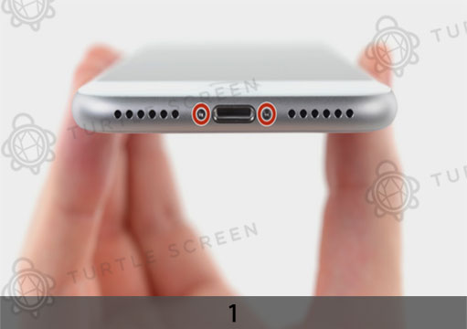
+ Remove the two 3.5 mm pentalobe screws from the bottom edge of the iPhone.
2. OPENING PROCEDURE
+ Heating the lower edge of the iPhone will help soften the adhesive securing the
display, making it easier to open.
+ Use a hairdryer and apply it to the lower edge of the iPhone for about 90 seconds in order to soften up the adhesive underneath.
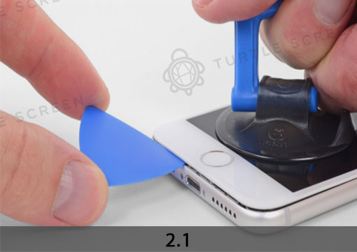
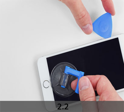
+ Apply a suction cup to the lower half of the front panel, just above the home button.
+ Be sure the suction cup does not overlap with the home button, as this will prevent a seal from forming between the suction cup and front glass.
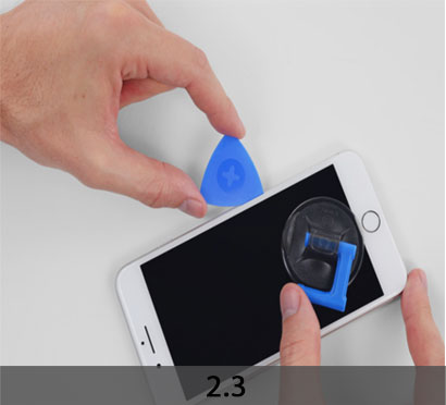
+ Pull up on the suction cup with firm, constant pressure to create a slight gap between the front panel and rear case.
+ Insert an opening pick or other thin pry tool a few millimeters into the gap.
+ The watertight adhesive holding the display in place is very strong; creating this initial gap takes a significant amount of force. If you’re having a hard time opening a gap, apply more heat, and gently rock the screen up and down to weaken the adhesive until you create enough of a gap to insert your tool.
+ Slide your pick around the corner and up the left edge of the phone, moving towards the volume control buttons and silent switch, breaking up the adhesive holding the
display in place.
+ Stop near the top left corner of the display.
+ Re-insert your tool at the lower right corner of the iPhone, and slide it around the corner and up the right side of the phone to separate the adhesive.
***Don’t insert the pick very far, or you may damage the display cables along this side of the iPhone. Insert it only a few millimeters, or about the width of the display bezel.
+ Gently pull up on the suction cup to lift up the bottom edge of the display.
+ Do not raise the display more than 15º or you’ll risk straining or tearing the ribbon cables connecting the display.
+ Pull on the small nub on the suction cup to remove it from the front panel.
+ Slide an opening pick underneath the display along the top edge of the phone to loosen the last of the adhesive.
+ Slide the display assembly slightly down (away from the top edge of the phone) to
disengage the clips holding it to the rear case.
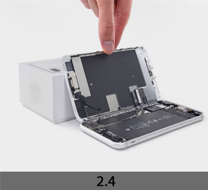
+ Open the iPhone by swinging the display up from the left side, like the back cover of a book.
+ Don’t try to fully separate the display yet, as several fragile ribbon cables still connect it to the iPhone’s logic board.
+ Lean the display against something to keep it propped up while you’re working on the phone.
STEP 2
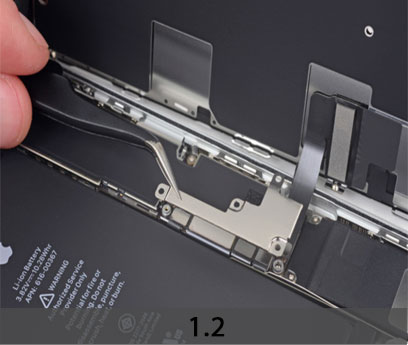
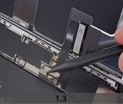
1. REMOVING BATTERY CONNECTOR
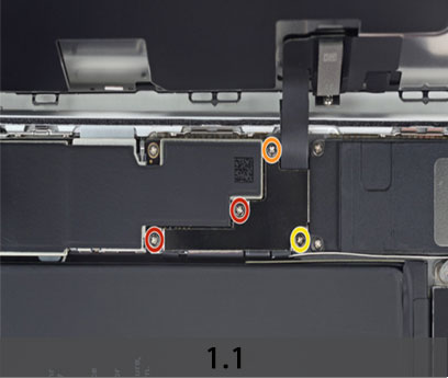
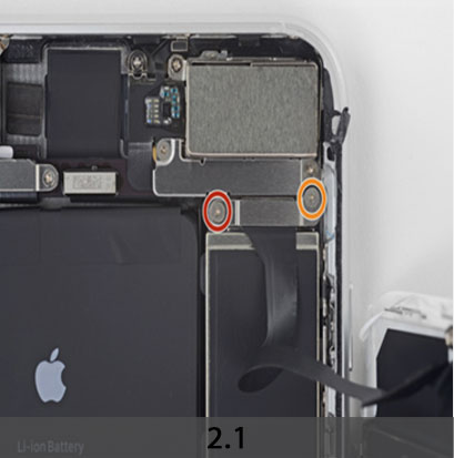
+ Remove four Phillips (JIS) screws securing the lower display cable bracket to the logic board, of the following lengths:
Two 1.3 mm screws
One 1.4 mm screw
One 2.7 mm screw
+ Throughout this guide, keep careful track of your screws so that each one goes back where it came from during reassembly. Installing a screw in the wrong place can cause permanent damage.
+ Remove the lower display cable bracket.
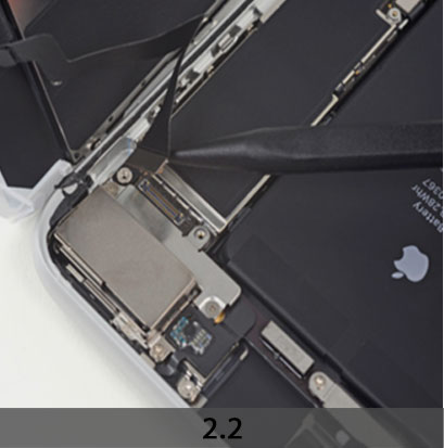
+ Use the point of a spudger to pry the battery connector up from its socket on the logic board.
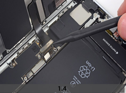
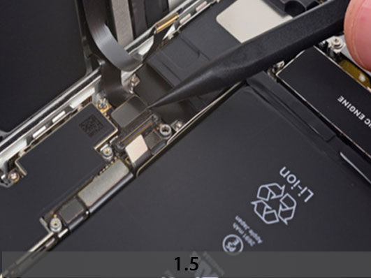
+ Bend the connector cable up slightly to prevent it from accidentally making contact with the socket and providing power to the phone during your repair.
+ Use the tip of a spudger or a fingernail to disconnect the large lower display connector by prying it straight up from its socket.
+ To re-attach press connectors like this one, press down on one side until it clicks into place, then repeat on the other side. Do not press down on the middle. If the connector is even slightly misaligned, the connector can bend, causing permanent damage.
+ Disconnect the second lower display cable connector, directly behind the one you
disconnected in the previous step.
2. Disconnecting the front panel sensor assembly connector from its socket
+ Remove the two tri-point Y000 screws securing the bracket over the front panel sensor assembly connector:
One 1.0 mm screw
One 1.2 mm screw
+ Remove the bracket covering the front panel sensor assembly connector.
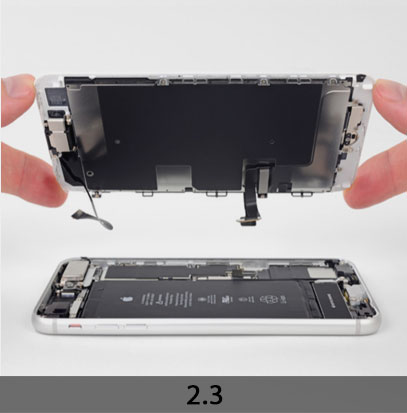
+ Use the tip of a spudger or a fingernail to disconnect the front panel sensor assembly connector from its socket.
+ Remove the display assembly.
+ During reassembly, pause here if you wish to replace the adhesive around the edges of the display.
STEP 3
REMOVE THE HOME BUTTON
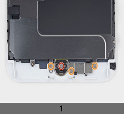
+ Remove the four Y000 screws securing the bracket over the home/Touch ID sensor:
One 1.2 mm screw
Three 1.3 mm screws
+ Remove the bracket that secures the home/Touch ID sensor.
+ Pry under the left edge of the home button cable connector to disconnect it from its socket.
***If the entire connector begins to flip up without separating, press down on the cable at the top edge of the connector with the flat of your spudger, while simultaneously prying up the left edge of the connector. Be very careful not to damage the cable or connector, or you will permanently disable the sensor.
+ Heating the area around the home/Touch ID sensor will help soften the adhesive
holding its delicate cable in place, making it easier to remove safely.
+ Flip the display assembly over. Use a hairdryer and apply it to the lower edge of the
display for about 90 seconds in order to soften up the adhesive underneath.
***Don’t overheat the display. It should be slightly too hot to touch comfortably.
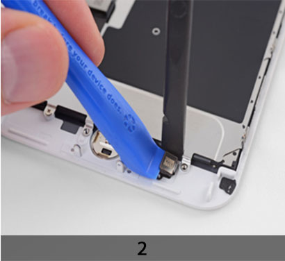
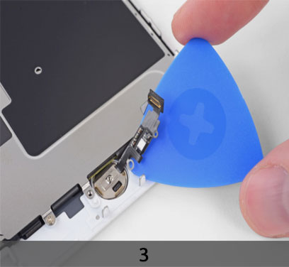
+ Use an opening pick to gently separate the adhesive holding the home/Touch ID sensor cable to the back side of the display panel.
+ Remove the home/Touch ID sensor assembly by lifting it through the front side of the display.
+ To reinstall, first feed the cable through the hole in the front of the display as shown.


