

CAUTION
Please follow this repair guide step by step or you made damage the phone.
Use the included magnetic match to organize loose screws by its correct positions. Wrong screws placement will irreversibly damage the logic board.
STEP1
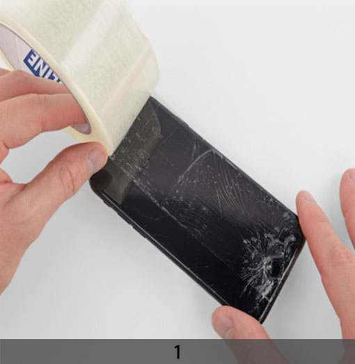
1. TAPING OVER THE DISPLAY
+ If your display glass is cracked, keep further breakage contained and prevent bodily harm during your repair by taping over the glass.
+ Lay overlapping strips of clear packing tape over the iPhone’s display until the whole face is covered.
+ This will keep glass shards contained and provide structural integrity when prying and lifting the display.
***Wear safety glasses to protect your eyes from any glass shaken free during the repair.
+ If the broken glass makes it difficult to get a suction cup to stick in the next few steps, try folding a strong piece of tape (such as duct tape) into a handle and lifting the display with that instead.
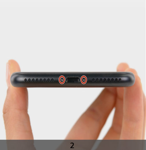
2. REMOVING THE PENTALOBE SCREWS
***Before disassembling your iPhone, discharge the battery below 25%. A charged lithium-ion battery can catch fire and/or explode if accidentally punctured.
Power off your iPhone before beginning disassembly.
Remove the two 3.6 mm P2 Pentalobe screws next to the Lightning connector.
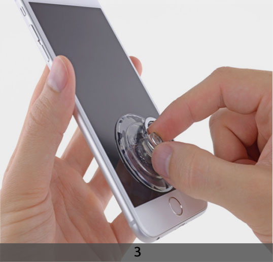
3. MANUAL OPENING PROCEDURE
+ Use a single suction cup to lift the front panel:
+ Press a suction cup onto the screen, just above the home button.
+ Be sure the cup is pressed securely onto the screen to get a tight seal.
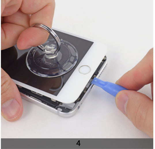
4. MANUAL OPENING PROCEDURE
+ While holding the iPhone down with one hand, pull up on the suction cup to slightly separate the front panel assembly from the rear case.
***Take your time and apply firm, constant force. The display assembly is a much tighter fit than most devices.
Using a plastic opening tool, begin to gently pry the rear case down, away from the
display assembly, while continuing to pull up with the suction cup.
+ There are several clips attaching the front panel assembly to the rear case, so you may need to use a combination of the suction cup and plastic opening tool to free the front panel assembly.
+ Pull the plastic nub to release the vacuum seal on the suction cup.
+ Remove the suction cup from the display assembly
STEP 2
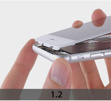
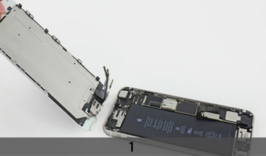
1. OPENING UP THE PHON
+ Pull the home button end of the front panel assembly away from the rear case, using the top of the phone as a hinge.
+ Open the display to about a 90º angle, and lean it against something to keep it propped up while you’re working on the phone.
+ Add a rubber band to keep the display securely in place while you work. This prevents undue strain on the display cables.
+ In a pinch, you can use an unopened canned beverage to hold the display.
+ Several clips along the top edge of the front panel form a partial hinge, allowing the front panel assembly to swing open like a book.
+ During reassembly, align the clips just below the top edge of the rear case. Then, slide the front panel upward until its top edge is flush with that of the rear case.
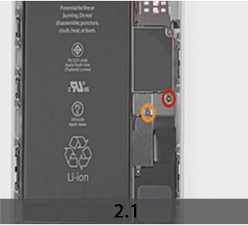
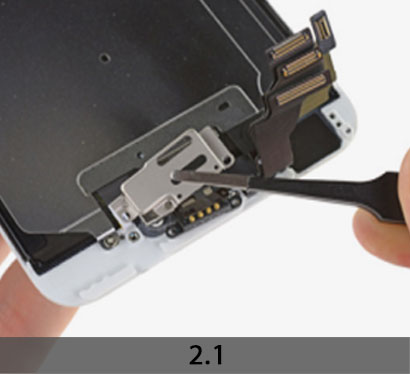
2. REMOVING BATTERY CONNECTOR
+ Remove the following Phillips screws from the
battery connector bracket:
One 2.3 mm screw
One 3.1 mm screw
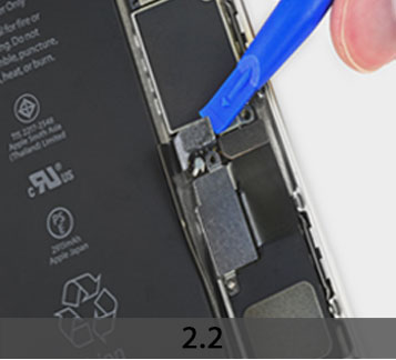
+ Remove the metal battery connector bracket from the iPhone.
+ Use a clean fingernail or the edge of an opening tool to gently pry the battery connector up from its socket on the logic board.
***Take care to only pry up on the battery connector, and not the socket on the logic board. If you pry up on the logic board socket, you may break the connector entirely.
STEP 3
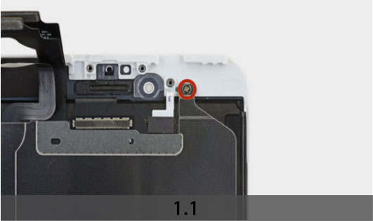
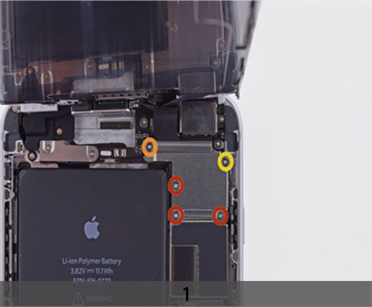
1. REMOVE THE FRONT PANEL ASSEMBLY CABLE BRACKET TO THE LOGIC BOARD
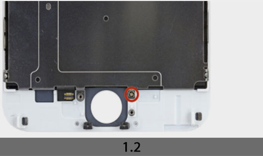
+ Remove the following Phillips screws securing the front panel assembly cable bracket:
Three 1.2 mm screws
One 1.5 mm screw
One 2.9 mm screw
***Do not attempt to insert longer screws into the red marked screw holes. Doing so may result in irreparable damage to the logic board.
+ Remove the front panel assembly cable bracket from the logic board.
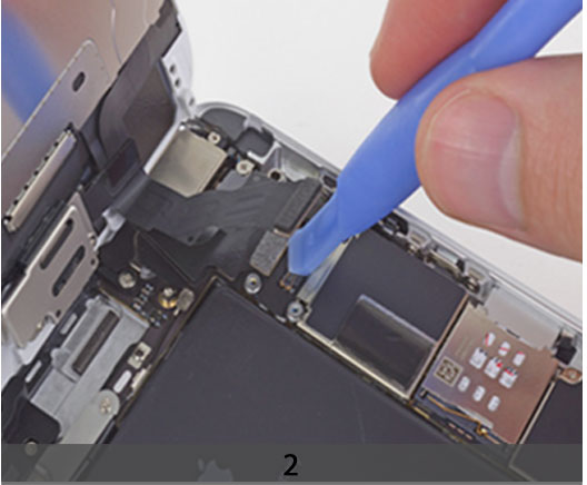
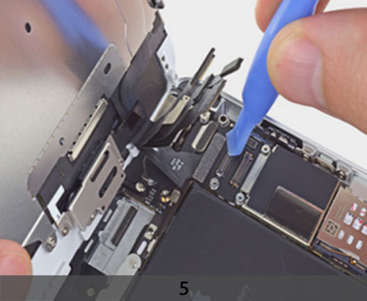
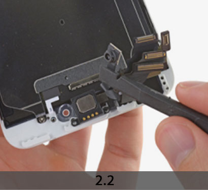
2. DISCONNECTING THE FRONT-FACING CAMERA AND EARPIECE SPEAKER CABLES
***In the next four steps, take care to pry up only on the cable connectors, and not on their sockets on the logic board.
+ While still supporting the front panel, use a fingernail or the edge of an opening tool to disconnect the front-facing camera and earpiece speaker cable connector.
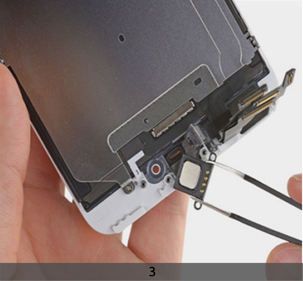
3. DISCONNECT THE HOME BUTTON CABLE CONNECTOR
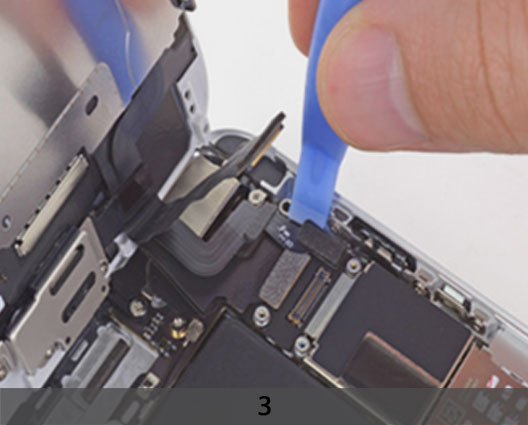
4. DISCONNECTING THE DISPLAY DATA CABLE CONNECTOR
***Make sure the battery is disconnected before you disconnect or reconnect the cable in this step.
+ Use a plastic opening tool to disconnect the display data cable connector.
+ When reassembling your phone, the display data cable may pop off the connector. This can result in white lines or a blank screen when powering your phone back on. If that happens, simply reconnect the cable and power cycle your phone. The best way to power cycle your phone is to disconnect and reconnect the battery connector.
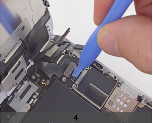
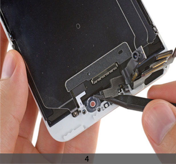
5. DISCONNECT THE DIGITIZER CABLE CONNECTOR
+ When reconnecting the digitizer cable, do not press the center of the connector. Press one end of the connector, then press the opposite end. Pressing in the center of the connector can bend the component and cause digitizer damage.
STEP 4
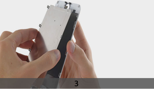
1. REMOVE THE FRONT PANEL ASSEMBLY FROM THE REAR CASE
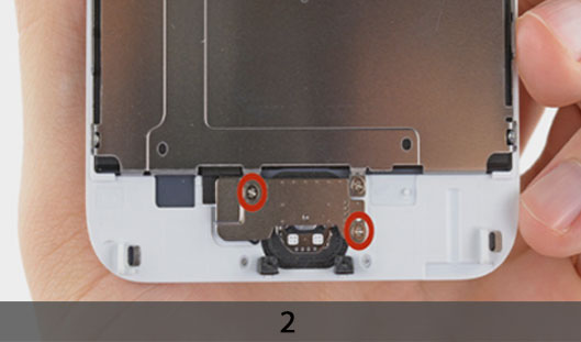
2. REMOVING THE HOME BUTTON BRACKET
+ Remove the two 1.8 mm Phillips screws securing the home button bracket to the front panel.
+ Remove the home button bracket from the front panel assembly.
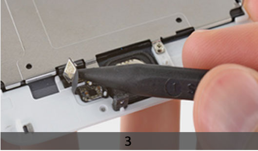
3. USE THE TIP OF A SPUDGER TO DISCONNECT THE HOME BUTTON CONNECTOR FROM ITS SOCKET ON THE HOME BUTTON CABLE
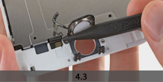
4. REMOVING THE HOME BUTTON
+ Carefully wedge the tip of a spudger underneath the home button connector cable.
+ Gently move the spudger across to separate the home button connector cable from the adhesive securing it to the front panel assembly.
***If the cable doesn’t separate easily, apply heat using a hair dryer to soften the adhesive, and try again. Be careful not to damage the cable.
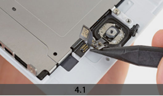
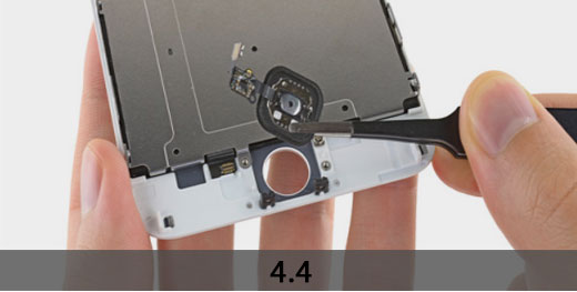
+ Using your fingertip, gently push, but do not remove, the home button up from the
opposite side to free one edge of the home button gasket from the front panel.
***Do not push the home button all the way through—you only need to get a corner free, so that you can pry it free with a spudger.
+ The rubber gasket surrounding the home button is very thin. To prevent the gasket from tearing, we recommend applying a minimal amount of heat.
+ Carefully run the tip of a spudger underneath the perimeter of the home button to
separate it from the front panel assembly
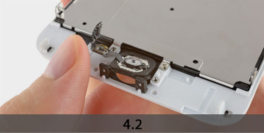
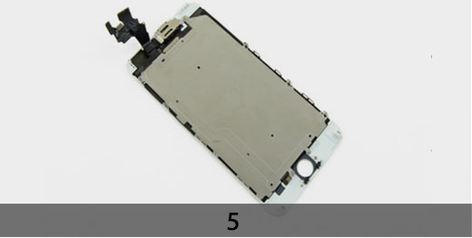
+ Lift and remove the home button assembly off the front panel assembly
5. TRANSFERING THE HOME BUTTON ASSEMBLY FROM OLD DISPLAY TO NEW DISPLAY
+ Display assembly remains.
+The Touch ID function will ONLY work with your phone’s original home button assembly, so you’ll need to transfer the home button assembly from your old display assembly to your new display assembly to retain Touch ID.
+ After reassembly, clean the touchscreen surface with an alcohol wipe prior to turning the iPhone back on. The alcohol helps dissipate any lingering static electricity, which can cause problems with the display.
***After reassembly, connect the iPhone to an AC power source before turning it on for the first time. Once the iPhone has booted up successfully, you can disconnect the AC power.
STEP 5
1. EARPIECE SPEAKER
+ Remove the following Phillips screws securing the upper component bracket:
One 1.5 mm screw
Two 2.3 mm screws
2. REMOVING THE EARPIECE SPEAKER BRACKET
Lift and remove the earpiece bracket from the display assembly.
Use the flat end of a spudger to pry up the front-facing camera and display cables, and gently push them aside.
3. USE A PAIR OF TWEEZERS TO FIRMLY GRASP AND REMOVE THE EARPIECE SPEAKER FROM THE DISPLAY ASSEMBLY
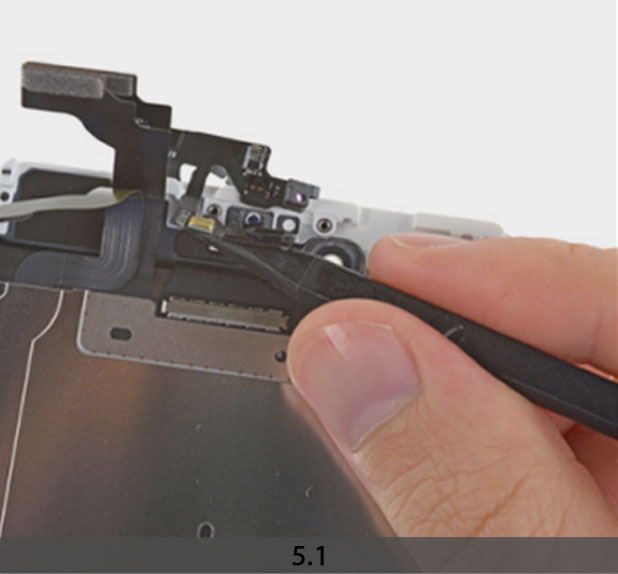
4. FRONT FACING CAMERA AND SENSOR ASSEMBLY
Use the tip of a spudger to gently pry up the sensor cable assembly from its recess in the display assembly.
The cable is held in place with a mild adhesive.
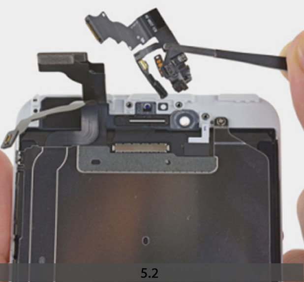
5. REMOVING THE FRONT-FACING CAMERA AND SENSOR CABLES
+ Pry the microphone portion of the front-facing camera and sensor cables from the display assembly.
+ Remove the front-facing camera and sensor cable assembly off the display assembly.
STEP 6
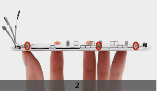
1. FRONT PANEL
+ Remove the two 1.7 mm Phillips screws (one on top and one on bottom) securing the LCD shield plate to the display assembly).
2. REMOVE THREE 1.3 MM PHILLIPS SCREWS FROM EACH SIDE OF THE LCD SHIELD PLATE (SIX TOTAL)
3. REMOVING THE LCD SHIELD PLATE
+ Carefully lift—but do not remove—the LCD shield plate by lifting the end nearest the earpiece speaker a few millimeters from the display assembly.
+ Gently lift the other end (nearest the home button) to peel the home button cable off the display assembly.
***Be extremely cautious as you peel the home button cable. It is a fragile cable. If you feel more than slight resistance, we recommend reheating and reusing the iOpener to soften the adhesive.
+ Remove the LCD shield plate off the display assembly.
+ Display assembly remains.