

CAUTION
Please follow this repair guide step by step or you made damage the phone.
Use the included magnetic match to organize loose screws by its correct positions. Wrong screws placement will irreversibly damage the logic board.
STEP 1
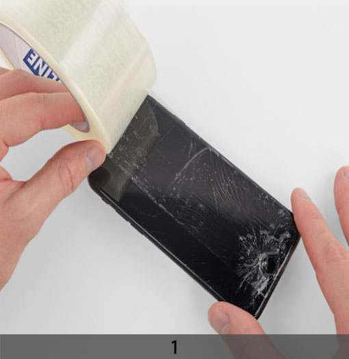
1.TAPING OVER THE DISPLAY
+ If your display glass is cracked, keep further breakage contained and prevent bodily harm during your repair by taping over the glass.
+ Lay overlapping strips of clear packing tape over the iPhone’s display until the whole face is covered.
+ This will keep glass shards contained and provide structural integrity when prying and lifting the display.
***Wear safety glasses to protect your eyes from any glass shaken free during the repair.
+ If the broken glass makes it difficult to get a suction cup to stick in the next few steps, try folding a strong piece of tape (such as duct tape) into a handle and lifting the display with that instead.
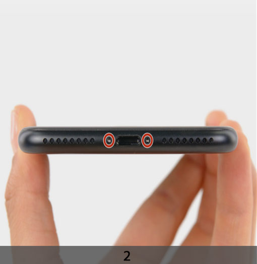
2. REMOVING THE PENTALOBE SCREWS
***Before you begin, discharge your iPhone battery below 25%. A charged lithium-ion battery can catch fire and/or explode if accidentally punctured.
+ Power off your iPhone before beginning disassembly.
***Opening the iPhone’s display will compromise its waterproof seals. Take extra care not to expose your iPhone to liquid damage after completing your repair.
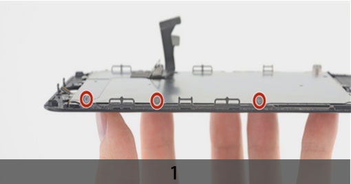
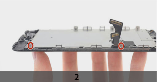
+ Remove the two 3.4 mm pentalobe screws at the bottom edge of the iPhone.
STEP 2
OPENING PROCEDURE
+ Heating the lower edge of the iPhone will help soften the adhesive securing the
display, making it easier to open. Use a hairdryer to apply it to the lower edge of the iPhone for about a minute in order to soften up the adhesive underneath.
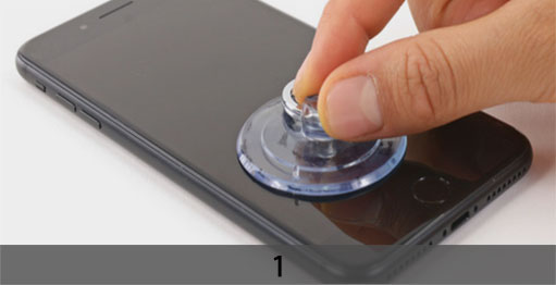
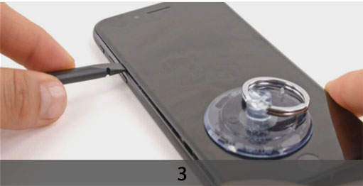
+ Apply a suction cup to the lower half of the front panel, just above the home button. Be sure the suction cup does not overlap with the home button, as this will prevent a seal from forming between the suction cup and front glass.
+ Pull up on the suction cup with firm, constant pressure to create a slight gap between the front panel and rear case.
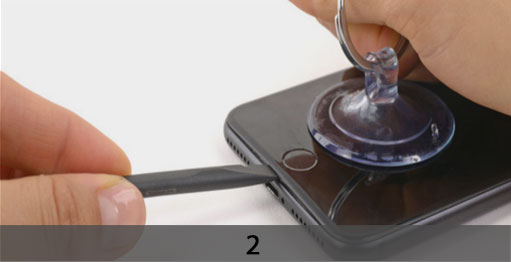
+ Insert the flat end of a spudger into the gap.
+ The watertight adhesive holding the display in place is very strong; creating this initial gap takes a significant amount of force. If you’re having a hard time opening a gap, rock the screen up and down to weaken the adhesive until you can fit a spudger inside.
+ While pulling up on the suction cup, twist the spudger to widen the opening between the screen and rear case.
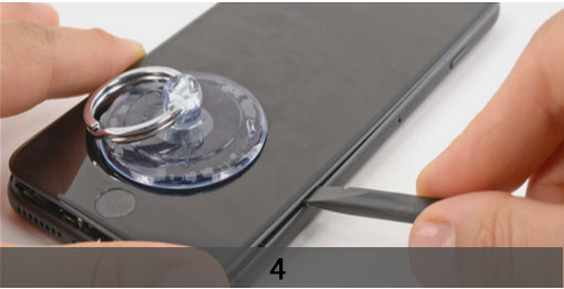
+ Insert the flat end of the spudger between the front panel and the rear case at the lower left edge of the iPhone.
+ Slide the spudger up the left edge of the phone starting at the lower edge and moving towards the volume control buttons and silent switch, breaking up the adhesive holding the display in place.
***Do not try to pry the top edge of the display away from the rear case, as it is held in place by plastic clips that may break.
+ Remove the spudger from the left side of the phone and insert the flat end into the bottom right corner.
+ Slide the spudger up the right edge of the phone to the top corner, breaking up the
adhesive holding the display in place.
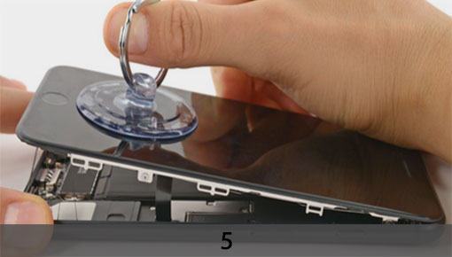
+ Pull up on the suction cup to lift up the display and open the iPhone.
***Do not raise the display more than 10º as there are delicate ribbon cables along the right edge of the device connecting the display to the logic board.
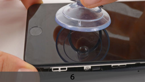
+ Pull up on the small nub on the suction cup to remove it from the front panel.
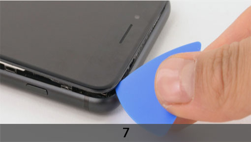
+ Slide an opening pick underneath the display along the top edge of the phone to loosen the last of the adhesive.
+ Pull the display assembly slightly away from the top edge of the phone to disengage the clips holding it to the rear case.
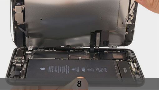
+ Open the iPhone by swinging the display up from the left side, like the back cover of a book.
***Don’t try to fully separate the display yet, as several fragile ribbon cables still connect it to the iPhone’s logic board.
STEP 3
REMOVING BATTERY CONNECTOR
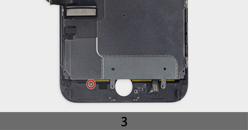
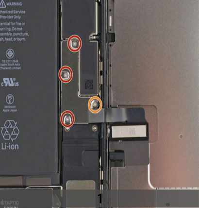
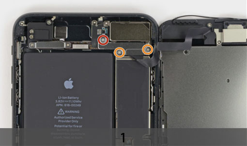
+ Remove the following four tri-point Y000 screws securing the lower display cable bracket to the logic board:
Three 1.2 mm screws
One 2.6 mm screw
+ Remove the lower display cable bracket.
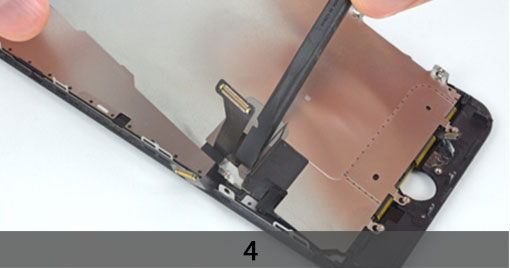
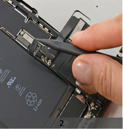
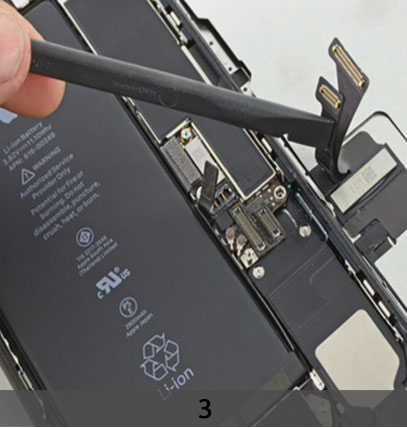
+ Use the point of a spudger to lift the battery connector out of its socket on the logic board.
+ Bend the connector cable up slightly to prevent it from making contact with the socket and providing power to the phone.
***Make sure the battery is disconnected before you disconnect or reconnect the cables in this step.
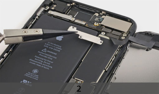
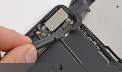
+ Use the flat end of a spudger or a fingernail to disconnect the two lower display
connectors by prying them straight up from their sockets on the logic board.
+ To re-attach press connectors, press down on one end until it clicks into place, then repeat on the other end. Do not press down on the middle. If the connector is even slightly misaligned, the connector can bend, causing permanent damage.
+ If you have a blank screen, white lines on the display, or partial or complete lack of touch response after reassembling your phone, try disconnecting and carefully
reconnecting both of these cables and make sure they are fully seated.
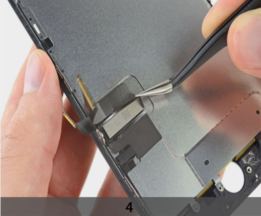
STEP 4
DISCONNECTING THE FRONT PANEL SENSOR ASEMBLY CONNECTOR FROM ITS SOCKET
+ Remove the three tri-point Y000 screws securing the bracket over the front panel sensor assembly connector:
One 1.3 mm screw
Two 1.0 mm screws
+ Remove the bracket.
+ Remove the two 1.3 mm Phillips screws securing the bracket over the front panel sensor assembly connector.
+ Remove the bracket.
+ Disconnect the front panel sensor assembly connector from its socket on the logic board.
+ This press connector should also be reconnected one end at a time to minimize the risk of bending.
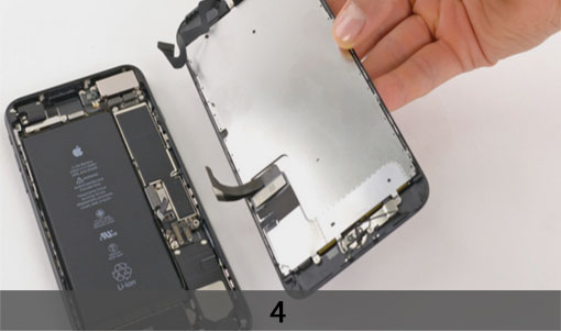
+ Remove the display assembly.
+ During reassembly, pause here if you wish to replace the adhesive around the edges of the display.
STEP 5
1. REMOVE THE EARPIECE SPEAKER
+ Remove the five Philips screws securing the earpiece speaker bracket.
Two 1.8mm screws
One 2.3mm screw
One 2.4mm screw
One 2.8mm screw
+ Remove the earpiece speaker bracket.
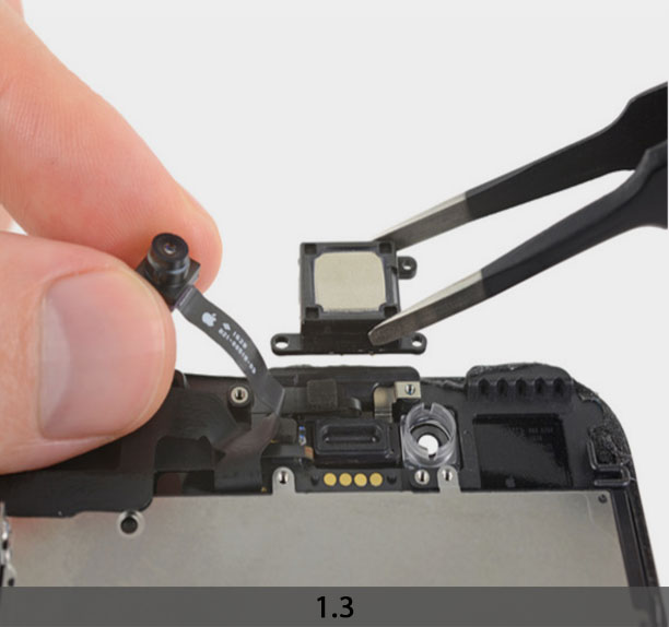
+ Use the flat end of a spudger to lift the front-facing camera from its housing.
+ Gently bend the camera ribbon cable to the side to clear the way to the earpiece
speaker underneath.
+ Remove the earpiece speaker.
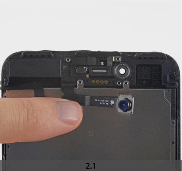
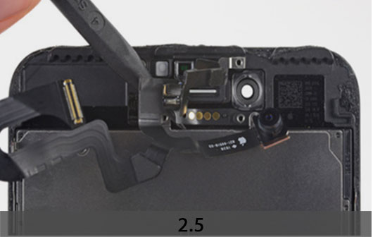
2. REMOVING THE FRONT CAMERA AND SENSOR CABLE ASSEMBL
+ Gently fold the camera and attached ribbon cable toward the bottom of the iPhone to allow access to the components underneath.
+ The sensors on this step are fragile. To increase your chances of removing them without damage, use your iOpener or hair dryer to apply heat to the upper portion of the display before you proceed. Alternatively, add a drop or two of isopropyl alcohol and let it
penetrate under the sensors before you pry them up.
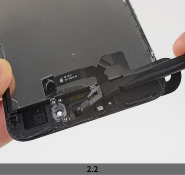
+ Slide a spudger under the proximity sensor flex cable, and lift the sensor out of its
housing.
+ Slide the tip of a spudger underneath the ambient light sensor flex cable, and lift the sensor out of its housing.
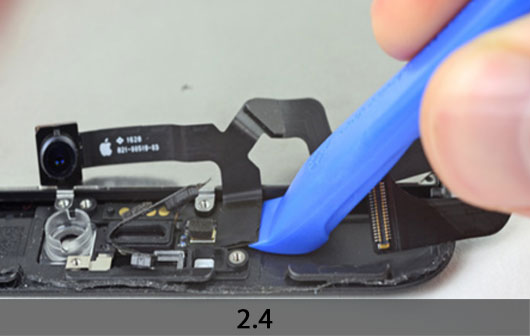
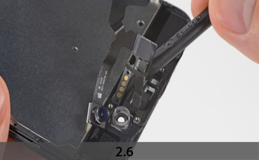
+ Insert the sharp edge of an iFixit opening tool underneath the camera assembly’s flex cable, on the opposite side from the front-facing camera.
***If necessary, use an iOpener or hair dryer to heat the top portion of the display and soften the adhesive securing the flex cable.
+ Pry up to separate the edge of the flex cable from the back of the display.
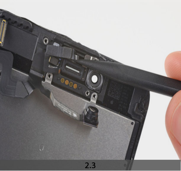
+ Insert the point of a spudger underneath the same portion of the flex cable that you
separated in the previous step.
+ Continue separating the remainder of the flex cable, pushing the spudger toward the strip of circular gold earpiece speaker contacts.
+ Continue using your spudger to carefully separate the last of the flex cable from the back of the display.
+ A piece of black double-sided insulating tape lies between the display and three rows of copper contacts on the back of the camera/sensor cable. It may remain stuck to the
display, or it may come off with the cable.
+ When reassembling, verify the tape is in place, or else cover the contacts on the back of the cable with an appropriate tape, such as Kapton tape.
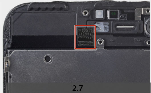
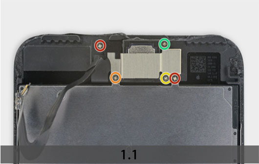
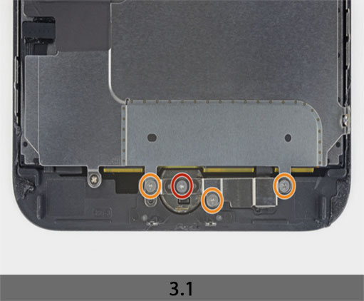
3. REMOVING THE HOME/TOUCH ID BUTTON
+ Remove the four Y000 screws securing the bracket over the home/Touch ID sensor
One 1.1 mm screw
Three 1.3 mm screws
+ Remove the bracket that secures the home/Touch ID sensor.
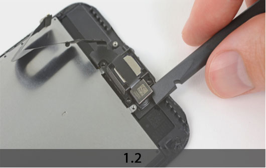
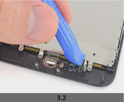
+ Pry under the left edge of the home button cable connector to disconnect it from its socket.
***If the entire connector begins to flip up without separating, press down on the cable at the top edge of the connector with the flat of your spudger, while simultaneously prying up the left edge of the connector. Be very careful not to damage the cable or connector, or you will permanently disable the sensor.
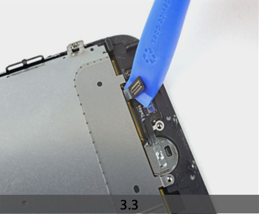
+ Carefully pry up the underlying connector and move it out of the way of the home/Touch ID cable.
***It’s very easy to damage your iPhone during this step. Work slowly and take care where you pry with your tool. If you damage the Touch ID hardware, it can only be replaced by Apple.
+ If the connector doesn’t pry up easily, use a hair dryer or iOpener to heat and soften the adhesive securing the connector, and then try again.
***Don’t try to detach the connector completely—simply flip it up slightly so that the
underlying home/Touch ID sensor cable can be removed.
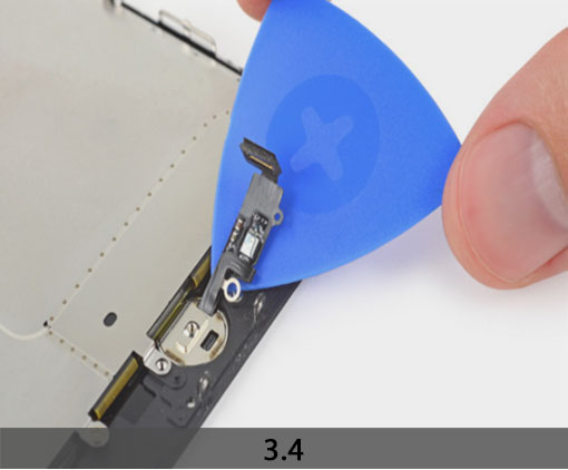
+ Use an opening pick to gently separate the adhesive holding the home/Touch ID sensor cable to the back side of the display panel.
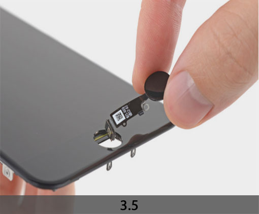
+ Remove the home/Touch ID sensor assembly by lifting it through the front side of the display.
+ To reinstall, first feed the cable through the hole in the front of the display.
4. LCD SCREEN AND DIGITIZER
+ Peel back the upper, rectangular portion of the LCD shield plate sticker to separate it from the flex cable underneath.
+ You don’t need to remove the sticker completely unless you intend to replace it.
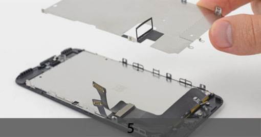
STEP 6
REMOVING THE LCD SHIELD PLATE
+ Use a Y000 driver to remove three 1.1 mm screws from one side of the display EMI shield.
+ Use a Y000 driver to remove two more 1.1 mm screws from the other side of the EMI shield.
+ Remove the 1.8 mm Phillips screw securing the EMI shield near the bottom of the
display.
+ Lift the LCD shield plate while pressing down on the flex cable it surrounds.
+ Feed the flex cable through the cutout in the LCD shield plate, being careful not to snag it.
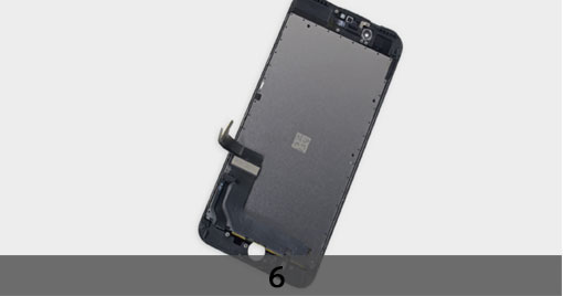
+ Remove the LCD shield plate.
+ Only the LCD and digitizer assembly remains.